Jan 252020
 

The first question is ‘why would you want to make nipples out of titanium?’   I guess the answer ‘ because its there’ isn’t really adequate!  I like it for several reasons – T5 is very tough and doesn’t deform when hammered by the cock, it is  completely corrosion resistant as isn’t marked by the cap composition or black powder residues and it doesn’t get ‘gas cut’ by escaping gas past the thread – plus it looks distinctive and I find it as easy or easier to use than a steel of adequate carbon content.  I’ve made lots for myself – almost all my shooting guns have titanium nipples, and I’ve made a number for clients and friends and haven’t had any negative comments.. As with steel nipples, I always wrap the thread with PTFE pipe tape before inserting the nipple.

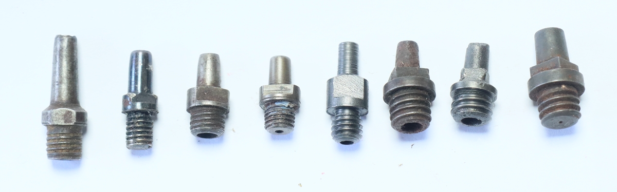
The one on the left is made from silver steel  – its a bit of a mess, the rest are titanium – much easier to make!

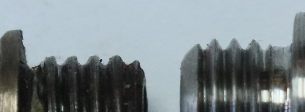
Most original gun threads are like the one on the left – the right hand one is a 1/4 x U.N.F. 28 t.p.i. thread in titanium.

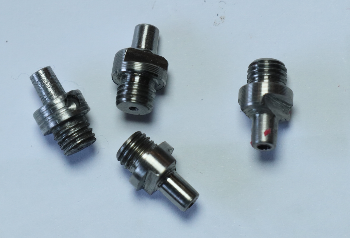
All nipples are not born equal!  Most don’t follow the current trend for small holes at the bottom – old caps were more powerful so it was probably less important.

WARNING:-  I do NOT recommend that you make nipples for a gun that is going to be shot unless you are a competent engineer and understand the risk attached to a nipple blowing out – a detached nipple is effectively a bullet out of YOUR end of the gun!  Always proof test any gun/nipple combination remotely.

Caution:-  Titanium burns and can be ignited during fierce cutting – only special extinguishers will put it out.  Swarf is usually continuous and sharp and very strong. Stop the lathe  often to remove swarf (use a paper towel to avoid cuts if necessary) and put in a metal bin.  If you start a titanium fire and don’t have a special extinguisher use sand.

Advice:- When cutting do not stop the feed with the tool in contact with the work – retract it before you stop the feed – or you will leave a mark and likely work harden the titanium. The same goes for drilling.  If you use coolant, flood the work to carry away heat, otherwise I use oil to drill small holes – any smoke acts as a warning.

I was looking on the web at comments on turning and milling T5 titanium and I realised that in my ignorance I had got on much better than the comments would suggest!  The only thing I knew before I started was that titanium swarf burns with intense heat and is difficult to extinguish – impossible with water.  I know that because we had a fire in swarf on a lathe in a workshop I was responsible for many years ago.  We called the Fire Brigade who unreeled their hoses until we told them titanium and water didn’t mix – in the end they took a bucket into the grounds and dug up some sand.  Titanium T5 bar ( the titanium alloy of choice) can be found on ebay as reasonable prices for offcuts from production runs in 10 and 12 mm diameters.   The problems with machining T5 titanium are several – its very elastic (Young’s Modulus low) so will deform out of the way of the tool, it work hardens dramatically so if the tool stops cutting and rubs it may not start cutting again easily, and the low thermal conductivity and heat capacity means that very little heat is carried away with the swarf but remains with the tool.   I have made many nipples of T5 and I guess that I have learned how to do it by trial and error.  I can turn it with cheap replaceable carbide tipped tools to get a slightly ribbed finish on the boss of the nipple, or with a sharp HSS tool to get a fine finish, but its difficult to take off very small cuts because the elasticity tends to deform the metal out of the way.  I haven’t had too much difficulty drilling 1 and 2 mm holes up to 12 mm or so deep – if you stop the drill it does work harden but you can break through – it pays to use sharp/new drills – I found that Tracy tools sold Imperial 40 thou drills for £1 each whereas the equivalent metric 1 mm drills cost £3.00 – no contest so I got 5.  I break less drills than when I try to make nipples out of silver steel.  I am fairly careful to splash oil around when drilling and to clear swarf often – pull the drill out and don’t let it idle in the hole or it will work harden.  You need a smooth control on the tailstock thread so you can feel progress when using the 1 mm drill – I can tell even on my big lathe how it is going, and feel the breakthrough of the 2 mm drill into the 1 mm hole.

The most difficult part is putting an external thread on the nipple – you need a sharp HSS die and you cannot have several goes at getting the diameter down – you have to know what gap to set in the die with the wedge screw and go for it – unless you need to remove a significant go in your second try you’ll just end up swaging/work hardening the thread.  It is a pain to try cutting a thread with a blunt die – I used one for some time and couldn’t understand why it was as much effort to back off the die as to ‘cut’ it onto the work!  It is a good idea to turn up a dummy and cut the thread, then part it off and try it  in the breech before going through the whole process so you know how much to open the die.  I have opened dies up so far they break in attempts to get a better fitting thread – I have also run a TIG welder up the outside of the die by a hole to weaken it so it opens easier.  You will find that a standard die doesn’t cut up to the shoulder of the nipple so you can’t screw it in completely – you need to grind up a small tool (or use a parting tool) to undercut the thread at the top slightly.  You can also grind out surplus taper on the face of the die to let it cut a bit nearer the shoulder, but you will almost certainly still have to undercut with a tool.  Make sure that you get the thread length right by checking the depth of the hole in the breech and any nipple you removed from the gun – if you make the thread too long it will be the devil’s own job to shorten it once the nipple is finished, and if you make it too short you will be loosing security in the thread – try to get the bottom edge shaped to match the bottom of the hole if you can.  Having got the initial turning and threading done the nipple is screwed into a bit of tapped bar in the chuck and the nipple end turned using the top slide set to a taper of a couple of degrees – using the top slide complicates the use of the Digital ReadOut so you have to remember not to touch the leadscrew wheel – I can’t lock the saddle on my lathe unfortunately.  If you are making a slightly oversize nipple it’s a problem tapping the hole in your jig bar – you can sometimes do it by rotating the tap around the diameter at the same time as turning it. Getting the actual nipple to be a good fit in the cap is tricky because you can’t proceed in very small steps, and files are not that effective.  The nominal nipple diameter at the top for a 1075 cap is, I think, 4.20 m.m.   Having got the nipple blank turned I put in the flats with a file while its in the tapped bar in a vice because its too difficult to hold the nipple firmly enough for them to be milled – a file works (slowly!) although it doesn’t quite look as professional as it should.   We, the Anglian Muzzle Loaders, reckon that the most reliable configuration for a nipple is with a 1 m.m. to 1.2 m.m. (40 to 50 thou)  hole in the bottom extending 4 or 5 mm up the threaded part put in before bothering to cut the thread in case the drill breaks off in the blank, and a 2 to 2.2 m.m ( 80 or 90 thou) hole down from the top as you shape the actual nipple end.  If you use the tailstock wheel to advance the drill you can feel when it breaks through into the 1 m.m. hole and can then put the 1 m.m drill through to clear out the hole. Most nipples in English percussion sporting guns and pistols correspond to 1/4 BSF thread with 26 threads per inch, although the diameter is often worn somewhat oversize.  The thread profile used in guns is generally quite different from modern threadforms – it has a much lower angle, probably 45 to 50 degrees as opposed to 60 degrees for the BSF and a much more rounded top and bottom to the thread – this means that the thread depth as a fraction of the overall diameter is less, and may mean that modern male threads cut a bit small for the equivalent old hole..  Be aware that the 1/4 UNF is the only UNF thread that DOES NOT correspond in pitch to the equivalent BSF diameter – 1/4 UNF is 28 t.p.i.   The Smiths patent nipples I am copying use an oversize 1/4 by 28 t.p.i (UNF) which is a first for me.  If you have a breech with a very loose nipple you can recut the thread with a tap of a slightly bigger diameter but you really must keep to the same t.p.i.  Fortunately 9/32 BSF has the same pitch as the 1/4 BSF (26 t.p.i) so can be used for recutting those threads and making new nipples.  If tapping out the breech for a bigger thread you will almost certainly need to grind the end of a tap almost flat to cut down to the bottom of the hole – it may need two taps, a plug to start and a ground off plug to finish.

Jan 082020
 

Here are photos of  ‘O’ gauge model railway bits that I am keen to pass on to good homes – they came from my 90 year old father-in-laws father, so probably before WWII.  The are not in particularly good condition and all have been modified early in their life.  Almost all the wagons and coaches appear to be home built, one or two commercial, some from kits? but some scratch built ?  Most of the locos wind up and run. There is an oval of track using what I would regard as 1/2 curves and full straights, plus a few quarter straights – I recognise the track as Hornby. I am keen to find out who made the locos.  These  trains were run on an outdoor layout that ran around a garden – the oval of track is barely big enough – there are enough coaches to make a train 15 ft long although it would have had to have most of the engines coupled to pull it!   There were around  a dozen coaches and 45 goods wagons plus the 7 engines!  I suspect that the locos are from a couple of different manufacturers as they take different sizes of keys – I don’t have original keys for any of them and the keys I do have (ex clocks) mostly don’t fit.

Loco No 1

Loco No 2

Loco No 3


Loco No 4

Loco No 5


Loco No 6

Loco No 7

Wagon parts etc – need axles, wheels from the box of bits!


there are half a dozen similar coached with different class configurations etc, and a number of scratch built LMS coaches.

Jul 062016
 

Land Cruiser steering lock problem is here if you really want to know!

June 2018 – Had an email from someone who had broken off the die cast link rod connecting the key assembly to the electrical switch and the steering lock – the usual problem!   Contrary to popular view I think its a relatively easy job for a mechanic or an enthusiastic amateur  provided you still have a working key- you first need to remove the plastic dash bit around the column so you can get at things.  The lock barrel is held in by a peg underneath about 2 inches from the front of the lock – with the key in the off but not lock position ( I think that is the right position) you can push the peg in and pull out the barrel.  The first part of the link rod should come out- you may need to press the sprung slider on it to clear a ridge in the housing.  That leaves the broken off bit in the housing.  It is held in by a tab that needs to be rotated to the correct position to pass through a slot in the back of the housing BUT you can’t rotate it because the ignition switch assembly stops you  going far enough  ( I think it needs to go 90 degrees anticlock from teh lock position), so you have to take that off the back of the housing – 2 screws that I believe are difficult to remove ? –  the heads face the front of the car (disconnect the batteries at this point!).   Having got that off, you need to rotate the bit so that the broken end of the die cast shaft is a D shape with the flat surface horizontal and at the top ( the V shaped cam that works the steering lock should point up and be on the left side of the centre) – a bit of jiggling should free it – you may need a fancy pair of very  long nosed pliers or something to be able to manipulate it  ( long reach 3 pronged spring grabber?) – I didn’t do that bit, the garage did it along with messing up the rest of the job. If you can see what you are doing, (mirror ?) its probably easier to rotate the bit and line up the key and slot from the back of the housing and push it through, then you just have to fish it out…   Once you get it out you need a new diecast bit ( I believe around £20) and put it all together again……..I didn’t do all of this job, but I have played around with the bits ( except the ignition switch)…………… good luck….


this is the bit that breaks off – you can see the V cam that moves the steering bolt pointing up and to the left  at the front- the part is almost in the right orientation to remove, it needs about 20 degees anticlockwise rotation! 

This is on its side – up is to the right – you can just see the keyway for the tab beneath the die cast link rod sticking through the housing – rhe flats on the end engage in the electrical switch.

This is on its side too

April 2017 – I still have a more or less full set of bits of the whole steering column and lock assembly that I think is pretty well perfect – minus the shear bolts – if you are interested please contact me via the comment box – Cambridge area.

Continue reading »

Jun 132016
 

Update – The SEIG X2 miller eventually packed up – the motor control board had been playing up for years, and I usually left it powered up but just not running, as that way it would run when I wanted it to!  Anyway I figured the motor control board was busted.   The motor says its 240 Volt A.C.  so I got a cheap A.C. motor controller from ebay that blew all the trips  in the house when I turned it on.   I got a replacement but all it did was to cause the motor to buzz and emit a whiff of smoke if I turned it up a bit.  I got out an old laboratory Variac – a rotary variable transformer giving from 0 to 260 volts A.C. and connected that but all I got was the buzzing – I didn’t dare turn it up very far.  The motor only had 2 wires going to it, so couldn’t be anything fancy, i.e. not 3 phase or feedback controlled or whatever, so the only thing left to try was D.C.   I got a 3 Amp bridge rectifier (ebay again) and wired it between the Variac output and the motor, with a switch and a fuse in the old control box on the front of the machine.  Success! it runs nicely from about 40 Volts and has much more torque at low speed than the original controller and is altogether much better – I haven’t tried it above about 140 volts as I haven’t needed to, but it runs very well – I’m not sure that I’d use the Variac’s ability to feed voltages above the mains voltage, and I’ll be careful when turning it to higher voltages for the first time.   If you have an old SEIG X2 with a motor that says 240V A.C. and has two wires (plus a yellow/green earth) going to the motor and you have trouble with the control board, look on ebay for an old  Variac, or Variable transformer capable of 2 or 3 Amps or more, and connect it up via a 3 amp 400Volt bridge rectifier.  I took the potentiometer out of the original control box and drilled out the hole and replaced it with a two pole single throw switch using ‘faston’ blade terminals…. Wish I’d done it years ago!  The Variac  will be too big to mount on the machine so it will have to sit on the bench or a shelf – but that is a small price to pay for getting the machine working again, and you can’t buy anything much better for the price…

I’m still left wondering what the original control board did with all its complicated circuitry?

old post……

I have a small  Axminster  SEIG X2 milling machine ( the same miller is widely sold under different brands) that is 5 or more years old.   It is a bit wobbly and weak for cutting steel, but I can usually manage by taking small cuts, although it does chip tools occasionally when the work jumps into the tool particularly if I forget and cut in the wrong direction.  For a long time it has had an annoying problem with the motor drive circuit – the speed control potentiometer has a switch to turn the power on, but you have to wait some variable time between switching the pot on and advancing it to run position or it doesn’t run at all.  The delay is a bit variable, between a few seconds and a couple of minutes when its first turned on.  I gather from the internet that this is a known problem.   I’m going to have a go at finding the problem – a timing issue of seconds to minutes that gets shorter as the circuits warm up suggest electrolytic or tantalum capacitors as the source of the problem, but I’ve failed so far to find a circuit diagram of the circuit on the board.   Axminster will sell me a board for £101 but don’t have facilities to repair boards, so I am challenged to find a solution… watch this space as I flounder around……

I took my testmeter into the shed and had a look at voltages – the speed control pot has -5.7 Volts across it, and when it starts properly the voltage stays at -5.7 at all speeds.  If its not starting as you turn the pot, the voltage drops to about -4 V at ‘full speed’ position.  The back of the board is a mass of surface mount stuff, so I’m not sure I can work out the control circuitry – there are a couple of multipin I/Cs that don’t have numbers on them, but I’m pretty sure the problem is in the very first stages of the speed control  – I just need some way of pinning it down a bit….


Well, I didn’t find anything wrong, but whatever I did or didn’t do, it is now much better and starts almost instanly 90% of the time – I begin to believe some of the comments on the web concerning bad joints….  A mystery, but since its functioning I will use it and worry when it goes wrong again….


May 202014
 

I am putting this up in case anyone needs to do the same – I have a SIP P178 HF welder and wanted to get lessons in precision TIG welding from Jason McDougall, who said that without a foot pedal control on the current and stop start I wouldn’t get very far!  Welders with foot controls don’t come cheap, and I didn’t want to scrap my almost new SIP, so I had a look around to see if I could fit a pedal control.  No info on the web that was relevant, although there were a few pics of pedals, and unfortunately no circuits available for that model.  Under the hood I found the current knob was a dual gang potentiometer of 1K Ohm resistance, which was a bit of a problem, as I would have to substitute my pedal for this potentiometer  – I couldn’t find suitable 1K slide potentiometers to make my pedal from, so ended up with a bit of a Heath Robinson arrangement with a cord running round a drum that sat between two 1K rotary potentiometers moved by an arm on the pedal – after a bit of messing about I put in a sprung idler pulley to keep tension on the cord and a microswitch that operated right at the top of the pedal movement – doesn’t quite cover the full range of the pots but probably goes to 120 amps – so far so good….


footpedal

Continue reading »