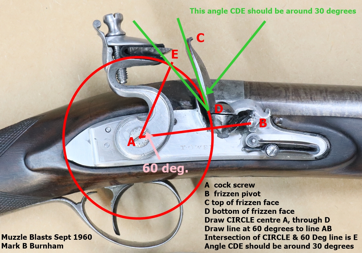
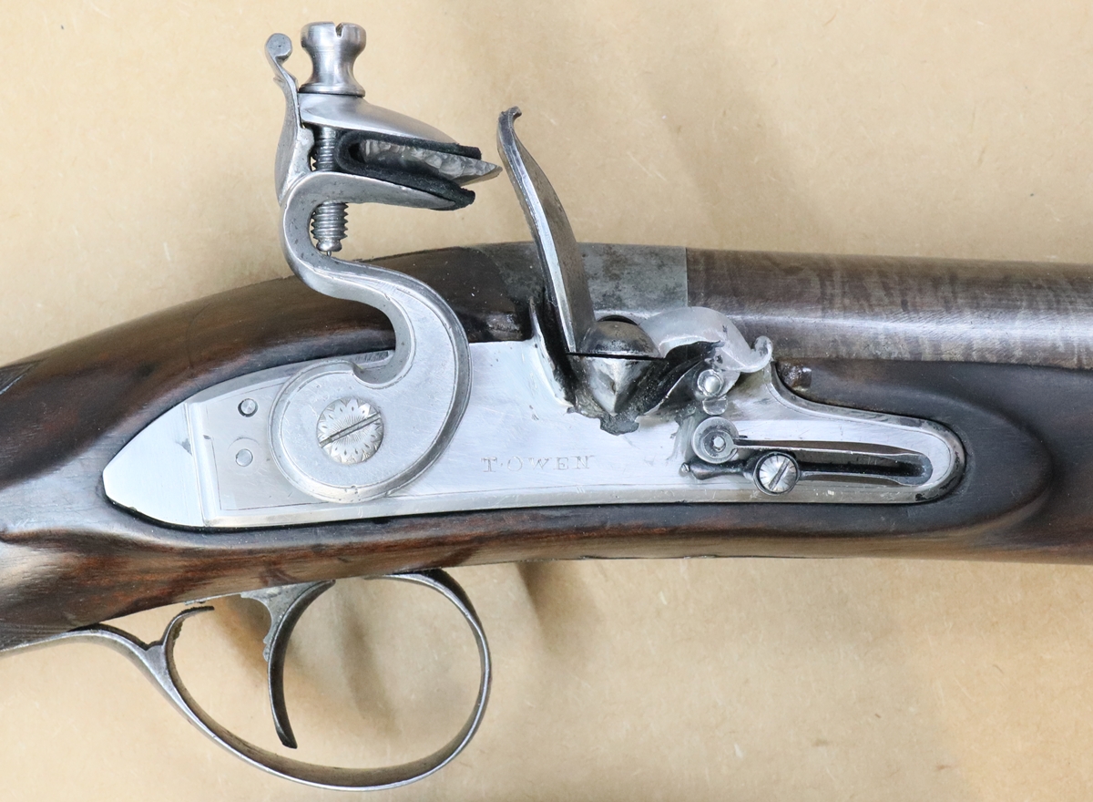
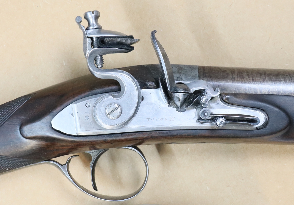
23rd Jan. Just had a delivery of logs, so I’ll be OK in the workshop for a while! Here is the method of checking the strike angle of flints on frizzens, taken from an old copy of Muzzle Blasts. It clearly assumes that the cock is right for your lock so that the flint hits the frizzen somewhere near the top – usually between about 3/4 of the way up although the article doesn’t cover that aspect. You can either do the drawing on a good photo of your flintlock, or on a blank piece of paper – to do a paper drawing you need a school compass – draw a line and mark point A, measure of the distance between the cock screw and the frizzen pivot using the compass and mark on your line as point B. Use your compass to measure from the top of the frizzen face to the frizzen pivot and draw a bit of a circle on your diagram. repeat from the centre of the cock screw. where the circles cross is the position of the top of the frizzen – label that point C. Do the same for the base of the frizzen face – label the crossing point D. You now have all the information relating to your gun that you need. You will need a protractor or a 60 degree and 30 degree template, which you can make easily by cutting the corner off a square piece of card such that one side is 60 mm long and the other is 104 mm long. ( Tan-1 of 104/60 being 60 degrees). Now you can do the rest of the construction following the instructions on the photo. If you have lost your school compasses (careless, you’ll get a detention!)) then first draw in the 60 degree line, then mark along it a distance equal to the distance AD using a scrap of paper – that’s E. Job done…. ( detention: copy out one of the posts on this website in longhand, hand it in by Wednesday)
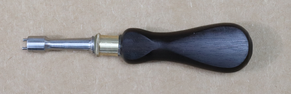
19th Jan Had a few days of going through the last year’s papers and trying to make sense of my tax return! Each day I reward myself if I make it to 16oo hrs with a cup of tea and an hour or so in the workshop. My project was to make a tool for unscrewing the Nock touch-hole – basically two tungsten pins in an EN 8 steel tool, mounted in a wooden ( Indian Ebony) handle with a brass ferrule. I made the first attempt, but the cheap digital readout on my little milling machine played up and I got the spacing of the pins wrong, so I had to make it again. I did find one other problem with the first one – I wanted to put the pins in with epoxy glue, but there was no way for the air in the holes to escape, so the pins kept coming out until I put it in a vice. So on the second try I was very careful to set the spacing of the holes right, and I drilled a small hole through the side joining the bottoms of the holes to let the air out. The shaft, brass ferrule and handle were of a classic 19th century design, but held together with a modern epoxy glue. Job done – I’ll put a few coats of Osma Top Oil on the finished wood – its a rather good oil finish that I used for all the worktops in the kitchen – it goes on as 3 or 4 very thin coats and dries as hard as iron ( well, nearly).
14th Jan Almost done all I can to the Nock until I can get out and shoot it – I hardened the steel, as the upright part of the frizzen is, or was, called but I still can’t get a spark – I will have to dig out a better flint. I may yet have to put a face on the steel. I made a touch hole today – I really only meant to do a trial run as I’m not very confident about screwcutting on my lathe and the thread isn’t anything you can buy a die for, being 9 mm diameter and 22 t.p.i – both pretty precisely. Anyway I fiddled about with the gearbox and gears and sorted out directions of travel etc. and chucked a piece of 10 mm titanium rod and did a test pass of a 55 degree tool – OK – it is 22 t.p.i, which is a good start! I started off putting a taper on the internal face with a centre drill, and drilling a 4 mm hole about 6 mm deep followed by a 1.7 mm drill in excess of the required length of the touch hole. Fortunately the thread I have to cut doesn’t have a shoulder so I didn’t have to start the thread abruptly, making it much easier as I could keep the leadscrew engaged all the time. I did a few passes cutting a bit deeper each time until it looked about right. If I had a collet set I could take the rod out of the lathe to test the fit and be sure to get it back exactly, but my chuck is not fantastic, so I took a chance and stopped the cutting. The thread was a tight fit in the barrel, but as the breech block was dead hard I didn’t mind using a bit of force to screw it in, and it seemed to go as far as the drum it was replacing had gone. Once I’d got it well in, I filed it off flush with the breech block and drilled a couple of 1.7 mm holes for pins to screw and unscrew it. I hope it works – the good news is that the touchhole finished up with the 4 mm drill ending about 1 1/5 mm back from the face – pretty well ideal. It fits the gun well, perhaps 1/2 a mm high in relation to the pan, but I hope nothing serious…. I guess a titanium touch hole is good? I’ve never had problems with titanium nipples so it should be OK, and I do love working with titanium! I now have to make a tool for unscrewing and screwing the touchhole – at the moment I’m using 2 TIG welding electrodes of tungsten – 1.6 mm diameter held in a pair of pliers!
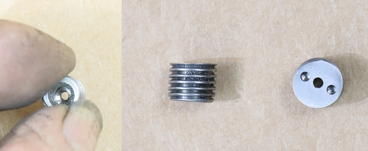
It looks as if the peaks of the thread were the tight bit – old threads were much more rounded in thread profile.
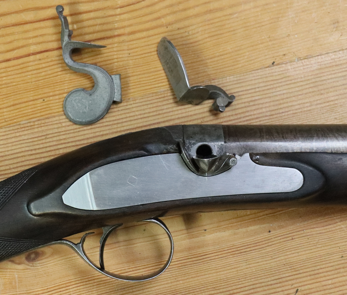
11 th Jan – One of those days when things don’t go to plan! I found I had to move the hole for the sear pivot in the lockplate by about .75 mm as I couldn’t get things to work. moving a tapped hole by a small amount is tricky, so I dropped a 5 mm end mill onto the new position and made a tight fitting plug with a slight taper and tapped it in from the outside and filed it flush on the inside so I could run a weld round the joint. My welder has a home made pedal controller on the current and it chose that moment for the potentiometer to go open circit and deliver 130 Amps when I touched the pedal with pretty dramatic consequences to both sides of the lock tail! I swapped back to the internal control and recovered the mess with a judicious bit of welding and a file! The I managed to break off a No 4 UNF tap in a hole – luckily I was able to extract the end of it! Then I drilled the hole for the peg on the mainspring and got it in the wrong place so had to plug it, weld over the back and drill a new hole. Last job of the day was to file the square in the cock – its a tricky job because there is not much tolerance on the angle of the square, or you get the cock positions in the wrong place, or the mainspring hangs below the edge of the lockplate when the cock is on its stop – there are fudges to put things right ( see other posts) but its nice to get it right first time. Its also tricky to get a good fit on the tumbler square and takes a lot of careful work with a square file. Anyway for once the square in the cock is dead right! If its a straightforward fitting of a cock onto a tumbler then I usually get it near and press fit them in a vice to form a tight fit, but in this case I want the tumbler to be usable with the percussion lock parts, so don’t want to deform it. I did have one other annoying problem in putting it together – I had very carefully marked the positions of the bridle, tumbler, sear pivot and sear spring using a steel jig but when I came to fit the sear spring I found that the lower spring blade was too long and hit the radius part round the pivot – I did grind a bit off on the grounds that it would still work with the percussion parts! I still have a little tidying up to do as the tail of the lockplate doesn’t fit snugly into the wood – the lockplate is a bit bent in the wrong way – not sure how I’ll tackle that as any bending of the lockplate will throw all the alignments off, but we’ll see.. I also have to make the touch hole – I’ll turn it out of titanium with a 22 t.p.i thread – I don’t think I can put any sort of head on it as I can’t/don’t want to touch the breech block (Its dead hard, and fits the nipple barrel for the percussion use). Anyway the lock fires well, the cock hits the frizzen and the frizzen flies open – I don’t get any sparks as the frizzen doesn’t have a hard enough surface and the flint is no good, but there is no reason why it shouldn’t spark well – there is lots of snap in the mainspring, and the frizzen flip point is just right…. we shall see… Altogether it has been an interesting project – given that I was just copying an existing percussion lock and using the internals you would think that it would all go together easily if you just copied the positions of the holes exactly – but for some reason, perhaps due to minor discrepancies or slight curvature of the plate, it was a real pig to get things to work! ( Of course the pan and frizzen and frizzen spring were items from the ‘spares ‘ box)
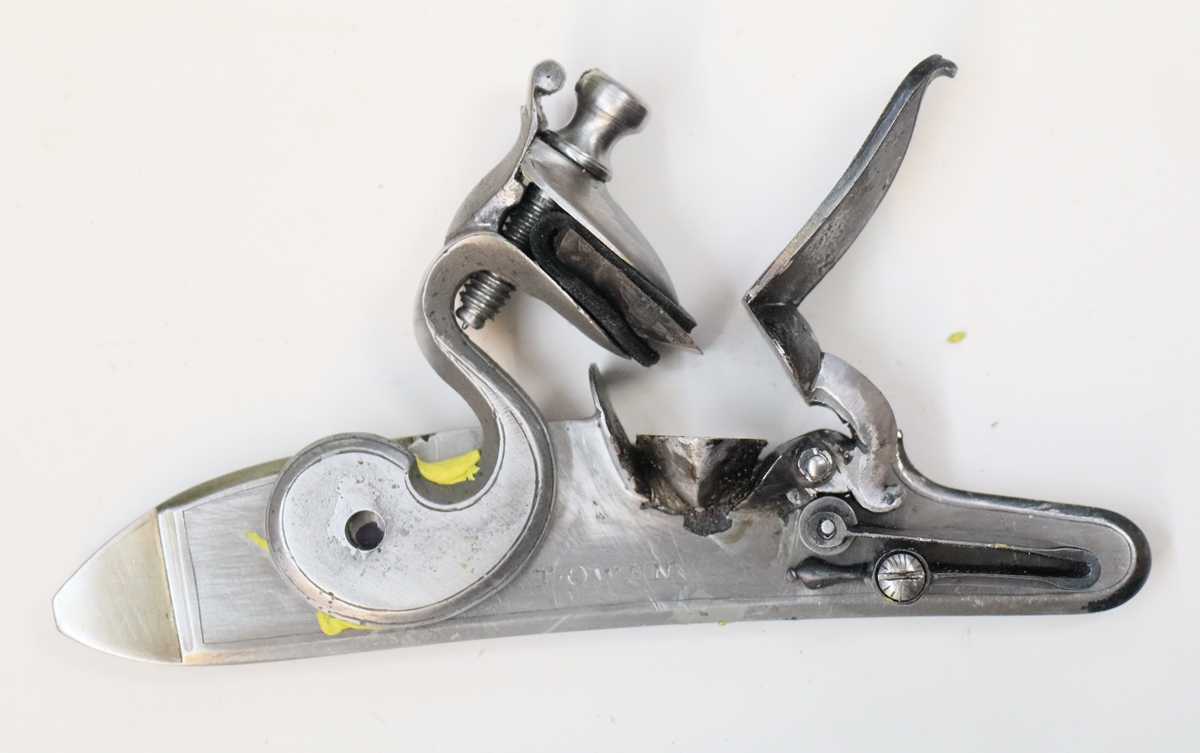
Half cock.
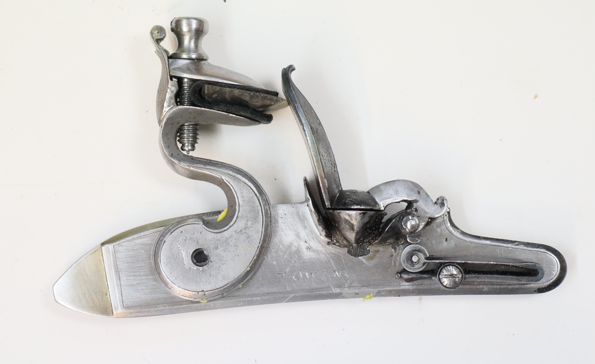
 Full cock.
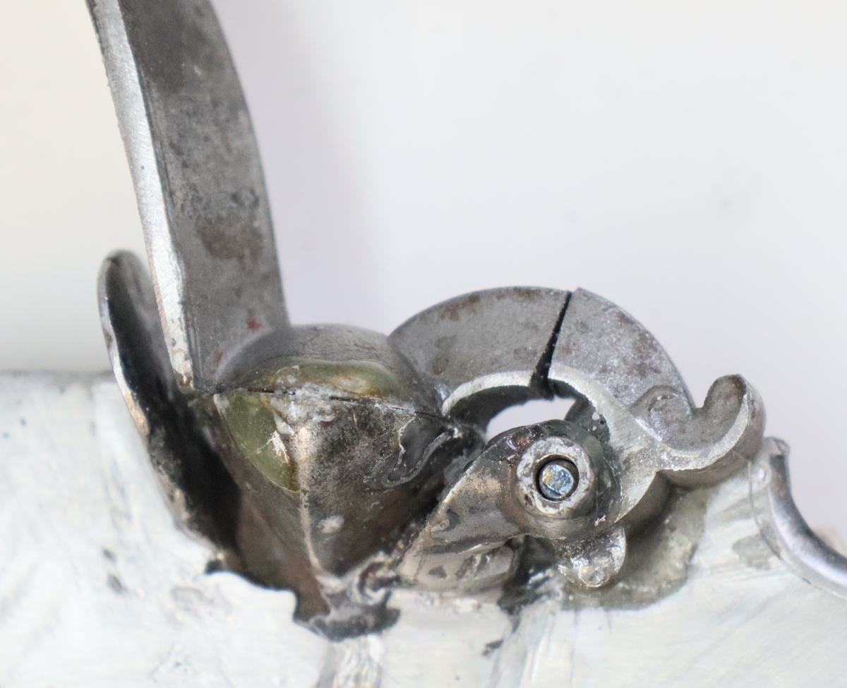

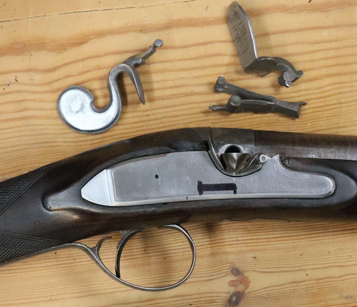
9th Jan – Started on the ‘works’ for the lock – I decided to begin by trasferring the parts from the original lock to my lockplate – I can replace them with new later. I made a spring steel jig from the original lock by making bits of steel rod into punches that exactly fitted the screw holes in the lock and marking and drilling the holes, then transferring the plate to the new lock and marking and drilling the holes in the lock plate. Unfortunately there is not a handy thread size to match the original screws – they are 3.05 diameter and 40 t.p.i. – between UNF 4 and 5, so I settled on 4 (2.85 OD) as it has to pass through 3.05 mm. holes – bit of a fiddle as the shanks are now slightly bigger than the threads so another diameter to turn… Anyway I made the 4 screws necessary and it all fits together – I probably need to remake the sear pivot screw as the shank is a bit slack, but that can wait. One of the things I find really tricky is getting the slots in the heads of screws exactly in the centre – I put the slots in by hand using a bit of hacksaw blade ground down to a tapered edge – I have a number of different degrees of grinding for different slot widths. Now I have to make the hole in the lockplate for the tumbler. Despite my very careful jig making I am not absolutely certain that the pilot hole in the lockplate aligns perfectly with the back bearing in the bridle – I realise I should not have put in a pilot hole, but left it til the bridle was in place and then drilled the lockplate through the bridle, but I’ll sort it – I may have to do a bit of adjustment of the hole position as I enlarge it to 7 mm for the tumbler ( I think it can only be 1/4 of a mm out.). Still its getting there! I will need to find my knife gravers to make the slot for the tab on the sear spring – everything got spread around when I vacated my workshop to be the kitchen!
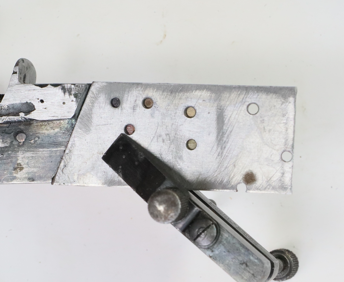
Jig is clamped and held by running instant glue round the edge.
I was quite pleased with the slots in the heads, I don’t usually get them that central! They are a bit too fine.
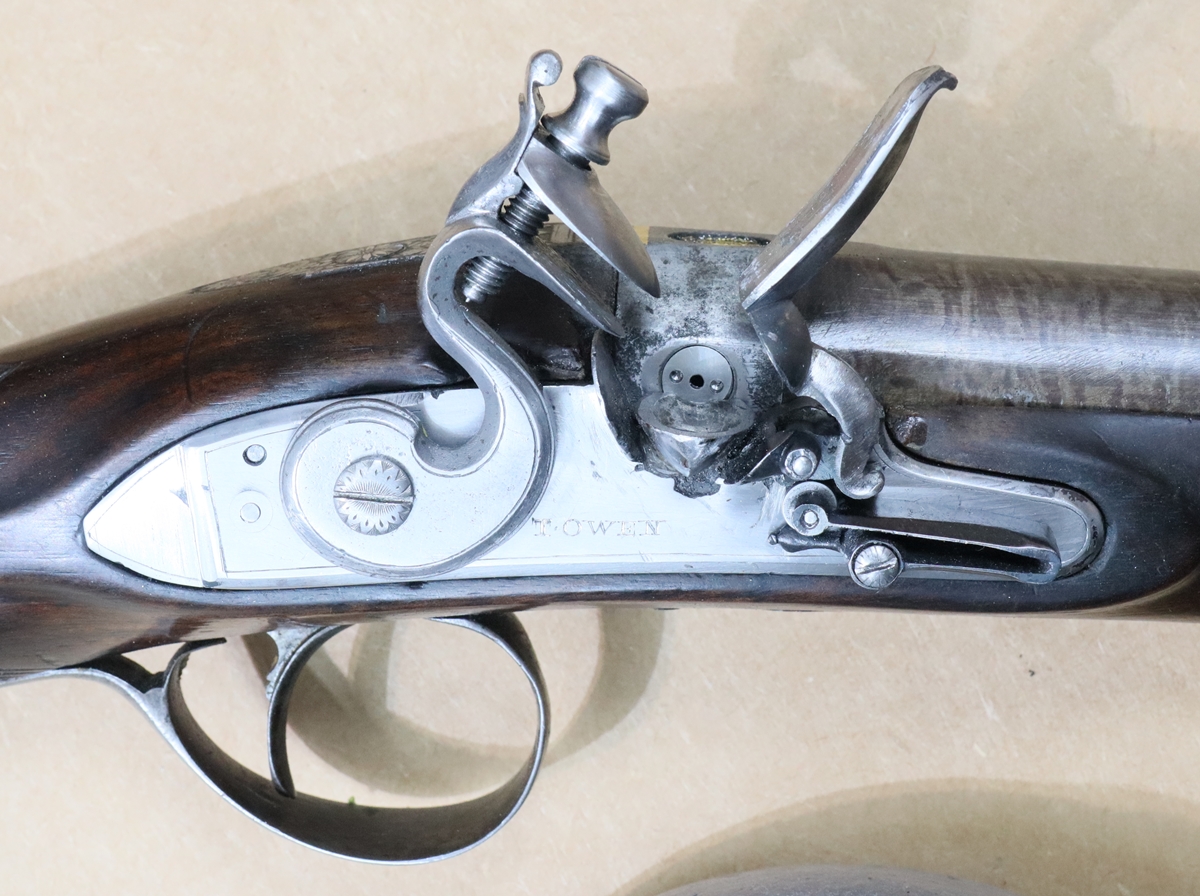
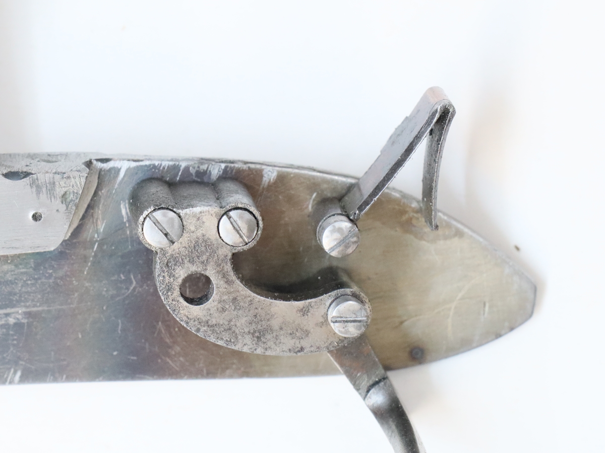
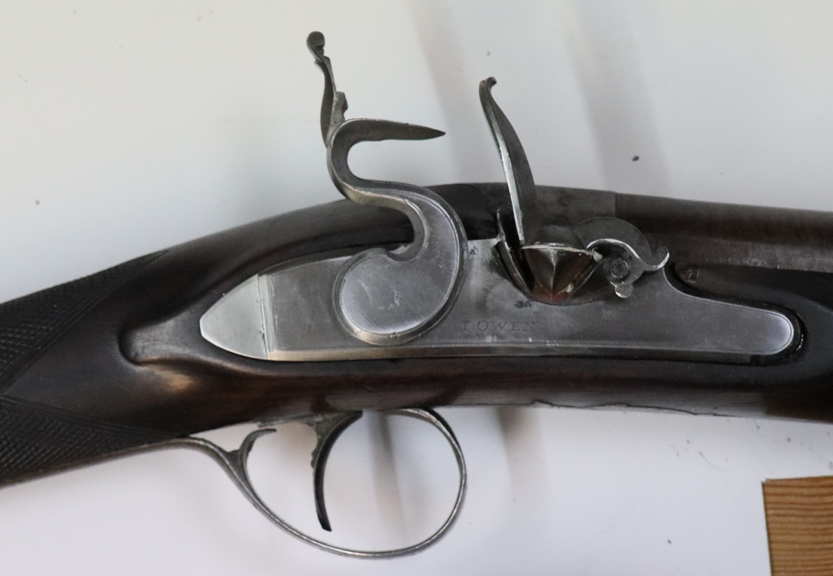
8th Jan – I retraced my screw making steps of yesterday! I managed to remove the bit of screw from the outboard frizzen pivot support by heating it with a tiny flame and cutting a minute slot and unscrewing it. I made the new frizzen spring fixing screw bigger, UNF 5 as the boss was big enough to accomodate it and it does take a lot of strain. Frizzen springs are attached at the lock plate face, but the force on them is where the frizzen heel touches the roller – i.e. outboard, so there is a force rotating the frizzen spring away from the lock – you often see it on flintlocks, not usually bad enough to worry. Anyway its all working nicely now. The spring closes almost completely when the pan opens – if I were making the lock again with the bebefit of hindsight I would have tilted the pan casting up at the front of the lock so as to leave a bit more room, but it seems to work. I’m still puzzled as to how the screws got to be so hard! I tempered the bit of the frizzen pivot up to 300C for a good 15 minutes but it still snapped when I tried to bend it. at a rather low level of force. I didn’t harden or temper the new screws! I ordered a selection of EN8 round bar so I have a stock of known material in future. I tried silver steel but its a pig to get a good finish when turning so I used the previous material. I reckon I can just get away with the cock in the same place as in the original lock – that will mean that I can copy all the internals ( or I suppose, use them interchangably between the two locks if I’m feeling lazy). Looking at the photos I’d say the cock was a bit big for the lock, but its not so obvious when looking at the real thing – I often see things when I come to put photos on the website that I miss in the flesh. Its good to have the photos on the blog – so often one (I) takes dozens of photos and never looks at them. Reminds me of the joke about some foreigh visitors – husband says “look at this fantastic view'”, wife says “just take a photo and I’ll look when we are back home”.
 The frizzen spring doesn’t have a lot of room, but is just OK!
Initial contact may be a little high, we’ll see how it works when finished.
7th Jan. – Its getting near to the time when I have to do my Tax for the year – but for the moment I can afford to play! Todays jobs went OK . I drilled and tapped the frizzen pivot hole and turned a pin with a UNF4 thread tapped into the outboard support. The inside hole was very close to the edge of the ‘bolster’ so it has a minimal head. I fettled up the frizzen spring and centered and drilled the hole through the boss and turned up a UNF4 pin with a countersink head to fit the outside of the frizzen spring boss ( an unusual arrangement) and turned up a small roller to bear on the toe of the frizzen pivot. The Frizzen pivot is quite low down on the lock plate and by the time the spring has a roller mounted there is not a lot of room for the spring to open and close. I closed the spring up in the vice so that its natural opening was a bit bigger than it would be with the frizzen open, but not excessively so – a bit of a guess! I heated the spring up to red heat with my oxy-gas torch (the one that supplied my Covid oxygen!) as my regular butane torch wasn’t hot enough when I brought it in from the freezing shed to properly vaporise the gas and dumped it in water, then polished it on the buffing wheel and found a spot on the AGA hotplate that was about 305 degrees (using a radiation thermometer) and put the spring down, covered with 3 layers of aluminium foil and closed the lid for 10 minutes to temper it. The screws and the roller were hardened using Blackleys colour case hardening powder – I stupidly tried the frizzen pivot screw without tempering it and broke off a bit of the threaded end in the hole – fortunately leaving enough to work, although it may give trouble in use. I just didn’t appreciate how hard/brittle EN8 could be! The tricky part was getting the holes to mount the frizzen spring in the right place so the bump on teh frizzen pivot goes through the null point at about 30 degrees opening and thereafter throws the frizzen back covincingly – I did manage to get that right although the spring might benefit from opening a bit to give a bit more snap – we’ll see when it sll together and we have the cock and mainspring etc working. Bother – I was sitting there opening and closing the frizzen when the frizen fixing screw sheared off – even after I had tempered it to 280 degrees, not sure what is going on – will sort out tomorrow and get some photos!
6th Jan Since we are now in lockdown I couldn’t go and get Jason our expert welder to weld in the pan, so I did it myself – it made a bit of a mess of the lockplate but it has cleaned up reasonably well given that the pan section didn’t have much of a margin and was thinner than the lockplate. It will work… Next job was to sort the frizzen – the nearest casting I had didn’t quite fit – it was either right for the pivot hole and wrong for the pan, or vice versa. I araldited the frizzen into the correct place for the pivot and drilled a 2.4 mm hole for a pin – just as I started to drill I saw that it wasn’t quite right, so had to pop the lock in the AGA to soften the araldite and start again. Having got a good pivot hole in the lock and frizzen, I cut the frizzen halfway between the pivot and the pan and filed the joint so that I could glue the pivot and the pan in place and tack weld the frizzen back together – that worked rather well, and even cleaned up reasonably – my only doubt is whether it will be strong enough in use. I filed up a rather large top jaw casting to fit – although why I didn’t just start from a bit of 6 mm plate as I usually do, is a mystery… Anyway that is done so I set up the cock and ran an end mill down the back of the top to clear the cock screw and tapped it No 12 UNC – I’d have preferred UNF but I don’t have a die for that size. I turned a matching top jawscrew from a scrap of EN8 16 mm round bar. With a bit of judicious filing on the back of the frizzen it now fits perfectly and holds a flint nicely, although I need to raise a few spikes on the gripping surfaces. Now I can see how the flint hits the frizzen and decide where to put the tumbler hole. I had a look at the lock of my John Manton double flint gun which has a similar shaped pan but a cock with a ‘spur’ – semi French ? – I have a very similar cock that I was thinking of using, but the spur cock would need the tumbler nearer the flash shield so it could act as a stop. I did some measuring – the arm on tumblers that carries the link to the mainspring defines the leverage and tends to be more or less the same length on all similar sized locks. This arm has to clear the ‘bolster, whose rearward extent is fixed by the poition of the side nail – this means that the distance between the side nail and the tumbler axis needs to be more or less constant. In my Manton the side nail is quite a lot closer to the touch hole than on my Nock lock, so the tumbler axis can be nearer the pan, hence the spur cock will fit. If you didn’t follow that, never mind, its another example of the inter-relationship between all the different bits of the lock – its no wonder that the designs stayed the same for long periods. With the frizzen in place if I put the cock on the original tumbler position the flint strikes the frizzen a little near the top, although I think it would work OK ( I seem too remember about 2/3 to 3/4 of the way up is usual – however, I’ve just had a look at the Manton and it strikes at exactly the same place on the frizzen as mine, so I won’t worry and will keep the same tumbler centre. Next job is to make the proper frizzen screw – The screw obviously passes through the frizzen as a plain shaft but can either be tapped into the outboard end of the frizzen support, or into the lockplate end. The Manton has the screw head on the outside and the thread in the lock plate, but I think its more usual to have the screwhead on the inside of the lock and the tapped thread on the support arm. I think I’ve also seen the scewhead on the inside of the lock, and a tapped larger thread in the lockplate so the end in the support arm is plain. I will probably copy the Manton. The screw that holds the frizzen spring can similarly either be tapped into the spring itself with the screwhead on the inside ( the more common arrangement ) or screwed in from the outside with the head visible. I have little choice as the spring casting I’ve got is intended to have the screwhead outside and I’m not sure there is enough metal to file it into the other pattern.. After that its the inside ‘works’.
I did a bit more filing before welding but you get the idea….!
Cock is in the position is in the original Nock lock – I think it is OK…
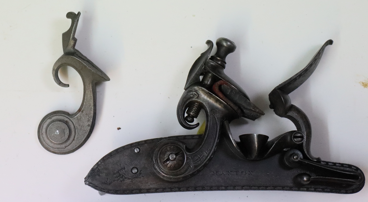
I rather wanted to use this spurred cock as on the John Manton but it won’t fit!
4th Jan I bit the bullet and engraved the name on the lock – more or less OK! I made the hook on the toe of the lock to go under the screwhead that retains the front of the lock – the lock plate is slightly curved so that the lock can be fed under the screw – I hadn’t noticed that before. My technique for the hook is to build up a pile of weld, then file it to shape – it ended up with a curved back as that is what the weld did – it works perfectly! I tacked the pan into the lock plate – it was a bit of a mess as I made a few mistakes that I had to weld over, but it turned out OK in the end – I have just left the critical joint under the pan on the front of the lock – I’ll need to be feeling confident to do that – my TIG welding is not very expert and I’m a bit out of practice. It all looks as if it is coming together – I need to make a top jaw and top jaw screw so that I can see exactly how the cock falls on the frizzen before I drill the tumbler hole, and put in the pivot for the frizzen. I’m not sure if there is enough metal in the frizzen in the right place for the pivot. I’ll araldite the frizzen to the pan and drill a small hole through the support bracket, frizzen and lockplate to see how they align. I’ll need to do a bit of sorting on the tail of the frizzen to get the lump that engages the frizzen spring to go through the slot cut in the pan support – another complication…… Makes you realise how complex and inter related all these bits are! And that still leaves all the internals and the frizzen spring……….

Photos not up to my usual standard, not sure what happened – sorry!
3rd Jan Still quite a lot of messing around finding all the bits of my old workshop that got moved out when it was a temporary kitchen, and putting them back. I had tmy engraving microscope, but not the hone that I need by it for sharpening gravers. I put the TIG welder and Argon back but then had to find the rinder to sharpen electrodes, and so it goes on! I filed the bevel/chamfer on the lock plate – more or less Ok, and did a bit of practice engraving on EN 8 to make sure I could cut the border lines well enough – I decided I could, so they are on the lockplate too. I cleaned up the cock so I could see how it fitted – I want to keep the same tumbler position as in the original Nock lock as it enables me to copy the shapes of all the internal components. I can’t, for instance, move the tumbler towards the pan as that would not leave room for the arm on the tumbler that carries the link to the mainspring, and shortening the arm would call for a stronger spring…. Its all interconnected! if I were just making a flint lock for display or a an ‘antique’ it probably wouldn’t matter too much, but my aim is to make a gun that shoots, and that has implications for the internal mechanism etc. The main issue for me is that some flintlocks fire really fast and are good to shoot, while others don’t seem t obe amenable to tuning for fast ignition – and it would seem that this is more art than science – indeed a black art!
2nd Jan – Dry fitted the pan into the lock plate, which took a lot of filing and trying – Its important to get the pan positioned correctly in relation to the touch hole – which is a little tricky as the touch hole itself hasn’t been made yet and the hole for it is 9 mm diameter. Its important that the touch hole is slightly above the pan because for fast ignition its the flash from the burning powder that ignites the main charge via the touch hole – the flash travels much faster than the burn rate through powder, so if you pile up powder over the touch hole you may get more reliable ignition but it will be slower than flashed ignition. my double Manton has little ‘shutters’ on the frizzens that cover the touch holes and push any priming powder away from the touch hole. The shutters have a small hole to allow air to escape but will (probably) keep any powder from the main charge from entering the pan. It was a Manton patent but never caught on. Anyway the pan is now ready to weld, but I think before I do that I’ll file the chamfers on the lock. I did try a cut with a graver on the lock material, but the EN8 seems harder than I remember, or else its so long since I engraved anything that I’ve forgotten what it feels like! (I probably need to anneal it! what a pain) I’ll probably put my name on the lock if I can cut it as I am not trying to pass it off as the work of Henry Nock!
1st Jan. 2021 – HAppy New Year – lets hope it improves rapidly, although the signs are not particularly good at the moment. Just hoping we don’t all go the way of Essex! I spent a few more hours filing and fettling on the Nock Lock – first core was to take a blank of 8 mm x 50 mm EN 8 steel ( this is moderately hardenable – ? about 1/2% carbon) and mill out the lock plate 3.5 mm thick leaving the bolster, then cut it out with an angle grinder and 1 mm disk. I clamped it on the bed of the milling machine and nibbled away some of the edges, then filed it to fit – have to be careful to work slowly and avoid damaging the edges of the lock pocket with burrs thrown up on the metal. Once profiled I put it back on the miller and thinned the tail down to about 1.6 mm and filed a concave step to match the original (its a common feature). So we now have a fitting lock plate with stepped tail and bolster in the correct place to receive the pan. At this stage its worth marking a centre punch for the side nail, as that will fix the plate relative to the gun – an easy way to do this accurately is to grind the blank end of a drill that just fits the hole in the stock and use it as a centre punch – it will not make a particularly good mark as its probably too soft, but you can see it clearly. At this point I could see that the bolster plus plate is the correct thickness and is touching the breech block – the breech block is slightly domed around the tapped hole for the barrel so I may need to recess the bolster to match as I can’t touch the breech block its – too hard. I eventually selected a pan casting that had already been cut down, and I’ve go a couple of frizzens that will probably fit, plus a couple of cocks. The net step will be to cut the lock plate to receive the pan casting – I may need to juggle the bolster and casting in the region of the frizzen pivot to make sure the pin is secure and works properly – the casting has been cut a bit close to the hole.. Having cut the plate for the casting I’ll clean up the plate properly and put a chamfer round the edge and do any engraving that is needed – its easier to do that before the pan is fixed in – I hate trying to engrave/re-engrave complete flintlocks as the pans always get in the way. Once the pan is welded in, or at least tack welded, I can finally sort out the frizzen, and then I’ll be in a position to select a cock – I have two possible ones, I think one is a little on the small size and the other may be a smidgin too big, but once the pan and frizzen are installed it will be easier to choose. It may be possible to open up the small one. Then I’ll be able to see where to put the tumbler hole – I have marked the original location from my card template but it can be altered slightly, although it can’t be pushed too far towards the tail of the lock or there isn’t room for the sear spring. There are so many variables to be sorted, and with a limited range of parts at my disposal, and only having made a couple of flint locks before it is a challenge – still that is why one does these things!
![]()
![]()
Possible parts – when the pan is in it should be easier to choose to best fit.
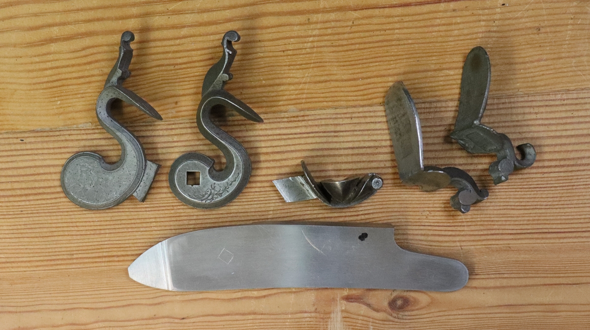
30th December – OK, its the new flint lock for my little Henry Nock – the pistols can wait! I got out my drawers of bits and pieces and had a rummage – I have 4 or 5 pan castings that Blackleys make for reconverting percussion back to flint from full lock sets, and several frizzens and cocks. Its a matter of sorting out which are most suitable period wise, and which are near enough in dimensions to fit – The original lock on the Nock looks as if it had a semi rainproof pan, not one of the very tiny pans that went with French cocks – I do have a set of castings for a late Mc Knight double with tiny pans and French cocks ( I don’t want to break up the set) – the cocks are tiny compared to earlier ones. I also have a pan section taken from the same lock and a somewhat larger flintcock with a spur that might do with the Mc Knight pan, and a frizzen that can be made to fit. Since I want the gun to be interchangeable between the new flintlock and the percussion lock, I dont want to modify the lock pocket or any of the woodwork, certainly not the opening. This means that the main defining dimension of a pan section is the overall thickness, as the pan needs to touch the breech accurately to avoid sparks getting iside the lock, while the outside of the pan casting lock face needs to be flush with the level of the existing lock face. I also have a pan casting that has been cut down ready to weld into a lock, but I’m not sure about it as the cut is quite close to the pan etc and I’m not sure if I can weld it neatly enough – I suppose I could get Jason in Haverhill to do it, but I’m trying to stay away form people while the pandemic rages! I guess that as I want the flintlock to shoot and am not trying to fake it back to flint, function is more important than looks!
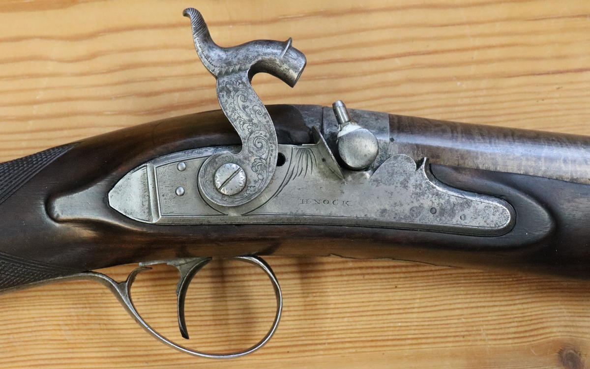
Strightforward drum and nipple conversion so not too difficult to make it into a flintlock that I can shoot.

These are the parts I picked out that might work for the Nock.